SCADA
The basics of Supervision Control And Data Acquisition
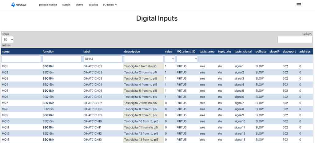
Digital Inputs
Any information coming from the field or installation that we are monitoring that can be represented as a binary entity, like True or False, Open or Closed , ON or OFF is what we usually call a digital input.
Such an entity may come from a simple switch on a site that let’s us know if a door is open or closed, or a circuit breaker that tells us of its position by having a contact that closes or opens. Or it may come from a complex controller that can be integrated in a local network and talks a certain protocol to a SCADA local unit and informs us of a status of a variable like “system in Auto mode” .
Whatever the origin of that signal, SCADA has a set of ways to process this signal and make sure the final user knows what he needs to do about it.
The base function is that of a mirror… represent in the SCADA database a binary value that follows the value of the real variable in the field. This is simple, looks very simple, but has some details into it that should be well managed.
A very important notion in a SCADA system is “time”. Everything that happens in the field, happens at a certain time. For a slow system, like water treatment, a second or a tenth of a second may be enough as a good resolution. But an electrical transmission system will require a millisecond resolution for most applications.
So every event or change of state in the field must be registered with a timestamp to allow future analysis and sorting of data.
Devices in the field are connected to SCADA system by electronic solutions that are usually very fast and detect every change of state. In many cases the field device does not change from Open to Closed in a clean way. It “bounces” causing the value to change from 1 to 0 to 1 to 0 a few times before stabilizing at 0. SCADA must be able to filter these events and ignore those bounces while transmitting and storing the correct information. This debouncing should be done as close as possible to the “edge’ or to the field device to avoid transmission of useless data through all the levels of the SCADA solution.
For each individual Digital Input that we process there are a set of variables that must be defined. This is done inside the SCADA database. In this case we named a table “digital_in” and store all this information there. This information covers topics as :
- Text label to identify the variable
- A short text for simplified reference
- The current value (0 or 1)
- Alarm definition
- Do we want an alarm when the value goes from 1 to 0?
- Do we want an alarm when the value goes from 0 to 1?
- What text to use on each of these situations
- Do we register or LOG each of these changes in our historic file.
- Specific text message for the Log register.
- The Digital Input can also be used to register and keep a value that does NOT come directly from the field, but can be DERIVED from a set of conditions. These DERIVED variables must have an easy way to be defined by the system integrator when setting up a SCADA solution.
In the section about Database Tables we will see the detail of all these parameters that will define how to handle each bit.
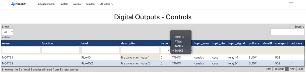
Digital Outputs
Digital Outputs, or Controls are commands sent to the field to control some external device. This is usually executed via relays that present a dry contact to the field wiring, allowing for electric isolation. This type of entity can be used as a PULSE output, that has a specified duration and is going to tell the device in the field to start or stop an action. They can be also a direct steady control, meaning that as long as the control is ON the relay is closed and the field action is maintained, like keep a valve on, and when the control is changed to OFF the relay is open and the field action is stopped, like keeping a valve OFF. The selection of the type of output to use is determined by the field device.
The type of information associated with a Digital Output has obvious differences to the DI.
- Text labels to identify the variable
- A short text for simplified reference
- The current state or value of the output. Note for pulse outputs this does not correspond to the position or status of the field equipment.
- The length of the pulse if used.
- Do we log the action and with what text.
- Usually there are no alarms associated with control actions, these are result of operator or automation functions. If you OPEN a circuit breaker you may have an alarm for zero voltage at he output, but not because of the control itself.